Products
-

RF Fixed Attenuator & Load
Features
1. High Precision and High Power
2. Excellent accuracy and repeatability
3. Fixed attenuation level from 0 dB up to 40 dB
4. Compact Construction – Lowest size
5. 50 Ohm impedance with 2.4mm, 2.92mm, 7/16 DIN, BNC, N, SMA and TNC connectors
Concept offering various high precision and high power coaxial fixed attenuators cover the frequency range DC~40GHz. The average power handling is from 0.5W to 1000watts.We are ability to match custom dB values with a variety of mixed RF connector combinations to make a high power fixed attenuator for your specific attenuator application.
-

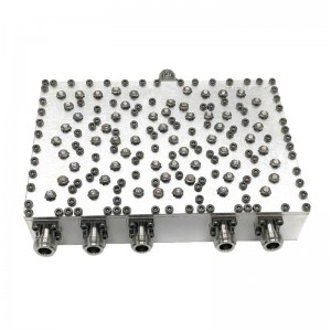
IP65 Low PIM Cavity Duplexer ,380-960MHz /1427-2690MHz
The CUD380M2690M4310FWP from Concept Microwave is a IP65 Cavity Duplexer with passbands from 380-960MHz and 1427-2690MHz with Low PIM ≤-150dBc@2*43dBm. It has an insertion loss of less than 0.3dB and an isolation of more than 50dB. It is available in a module that measures 173x100x45mm. This RF cavity combiner design is built with 4.3-10 connectors that are female gender. Other configuration, such as different passband and different connector are available under different model numbers.
-

SMA DC-18000MHz 2 Way Resistive Power Divider
CPD00000M18000A02A is a 50 Ohm resistive 2-Way power divider/combiner.. It is available with 50 Ohm SMA female coaxial RF SMA-f connectors. It operates DC-18000 MHz and is rated for 1 Watt of RF input power. It is constructed in a star configuration. It has the functionality of a RF hub because every path through the divider/combiner has equal loss.
Our power divider can split an input signal into two equal and identical signals and allows operation at 0Hz, so they’re ideal for Broadband applications. The downside is there’s no isolation between ports, & resistive dividers are normally low power, in the range of 0.5-1watt. In order to operate at high frequencies the resistor chips are small, so they don’t handle applied voltage well.
-
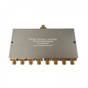
SMA DC-8000MHz 8 Way Resistive Power Divider
CPD00000M08000A08 is a resistive 8-way power splitter with a typical insertion loss of 2.0dB at each output port across the frequency range of DC to 8GHz. The power splitter has a nominal power handling of 0.5W (CW) and a typical amplitude unbalance of ±0.2dB. The VSWR for all ports is 1.4 typical. The RF connectors of the power splitter are female SMA connectors.
The advantages of resistive dividers are size ,which can be very small since it contains only lumped elements and not distributed elements and they can be extremely broadband. Indeed, a resistive power divider is the only splitter that works down to zero frequency (DC)
-
Duplexer/Multiplexer/Combiner
Features
1. Small size and excellent performances
2. Low passband insertion loss and high rejection
3. SSS, cavity, LC, helical structures are avaliable according to different applications
4. Custom Duplexer, Triplexer, Quadruplexer, Multiplexer and Combiner are avaliable
-

3700-4200MHz C Band 5G Waveguide Bandpass Filter
CBF03700M04200BJ40 is a C band 5G bandpass filter with a passband frequency of 3700MHz to 4200MHz. The typical insertion loss of the bandpass filter is 0.3dB. The rejection frequencies are 3400~3500MHz ,3500~3600MHz and 4800~4900MHz.The typical rejection is 55dB at the low side and 55dB at the high side. The typical passband VSWR of the filter is better than 1.4. This waveguide band pass filter design is built with BJ40 flange. Other configurations are available under different part numbers.
A bandpass filter is capacitively coupled between the two ports, offering rejection of both low frequency and high frequency signals and selecting a particular band referred to as the passband. Important specifications include the center frequency, passband (expressed either as start and stop frequencies or as a percentage of the center frequency), rejection and steepness of rejection, and width of the rejection bands.